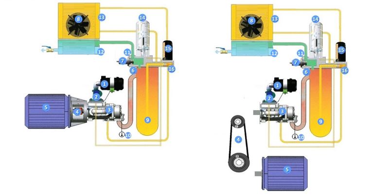
Compressor Operation Diagram
|
Direct Driven Screw Compressors |
Belt Driven Screw Compressors |
|
1. Air Filter |
9.Oil Tank |
|
2. Intake Valve |
10. Temperature sensor |
|
3.Screw Air End (made in Germany) |
11. Pressure Sensor |
|
4.Flexible Couplings for Direct Driven Compressors 4.Belt Driven System (Air End Pulley, Electric Motor Pulley and V Belts) |
12. Air/Oil Radiator air cooler side
|
|
5.Electric Motor |
13.Radiator oil cooler side |
|
6.Combination Block |
14.Air/Oil Sperator |
|
7.Minimum Pressure Valve |
15.Oil Filter |
|
8.Axial Cooling Fan |
16.Thermostatic Valve |
Air from the atmosphere is passed through the Air-Filter and the Air-Suction Valve. After that filtered air, mix with oil then compression event takes place at the Air-end. Two rotating screws compress the Air-Oil mixture via rotating at high frequency. Compressed Air-Oil Mixture enters into the Oil Tank. Oil goes to the bottom side of the Oil Tank. If the temperature of the oil is under 71 C, the oil goes through the Oil filter and goes into the Air-end again. If it is above 71 C, oil is sent to the Air-Oil Radiator. Cooled Oil passes through then Oil filter and goes into the Air-end. Air and tiny oil particles go to the Air-Oil Separator. At the Separator air is seperated from the tiny oil particles. Seperated air goes into the Air-Oil Radiator. So cooled air can go into Air Dryer now.